TDA2822 Stereo Audio Amplifier
An audio amplifier is an Electronic circuit that amplifies low-power audio signals to a level suitable for driving Loudspeaker. These Amplifiers are used in wireless communications and broadcasting, and in audio equipment of all kinds. There are many classes of Amplifiers and we have previously built a lot of Audio Amplifier circuits ranging from small 10W amplifiers to heavy 100W Power amplifiers.
In this project, we are going to build an Audio Amplifier using TDA2822 IC which is a very popular dual-channel audio amplifier commonly used to build high-power audio amplifiers. The TDA2822 Amplifier circuit will have one TDA2822 amplifier IC and will be able to drive two Speakers with volume control. Also, the audio input for our amplifier board can be provided directly from an audio jack. To build this TDA2822 Stereo Amplifier on a PCB, we have fabricated our PCB boards from PCBWay and we will assemble and test the same in this project.
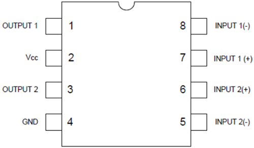
The TDA2822 is a dual low power audio amplifier IC that can be configured in stereo mode or bridge mode. It offers low crossover distortion, low quiescent current and is available in an 8 pin plastic dual in-line package. This IC can operate over a wide range of supply voltages ranging from 3V to 15V. It is specially designed for use in portable radios and transistor sets. It can deliver an output power of 0.65W per channel into a 4-ohm loudspeaker @ 6V supply voltage and 0.38W per channel into an 8-ohm loudspeaker @ 6V supply voltage in the stereo mode.
TDA2822 Specifications:
The complete TDA2822 Amplifier circuit is shown in the image given below. The schematic was drawn using EasyEDA. In addition to TDA2822M IC, it uses two potentiometers, two speakers, and some capacitors and Resistors.

The left speaker (Speaker1) is connected to output pin 1 of the IC through electrolytic capacitor C8. The right speaker (Speaker2) is connected to output pin 2 through electrolytic capacitor C7. The inverting input pins (Pin5 and Pin8) are connected to the ground through filter capacitors C1 & C3. The Non-Inverting Pins (Pin7 and Pin6) are input pins and are connected to potentiometers via electrolytic capacitor C10 & C11. The capacitors C10 and C11 are connected to block the passing of any DC component from the amplifier IC to the output load. Any DC component from the amplifier to the load which is the speaker in this case can damage it or produce noise or distortion in the output audio. The Pot1 & Pot2 work as left- and right channel volume controls for both the speakers. Pin 2 is connected to the DC supply and Pin 4 is connected to the ground. Electrolytic capacitor C2 is connected across VCC and ground pins work as a filter capacitor.
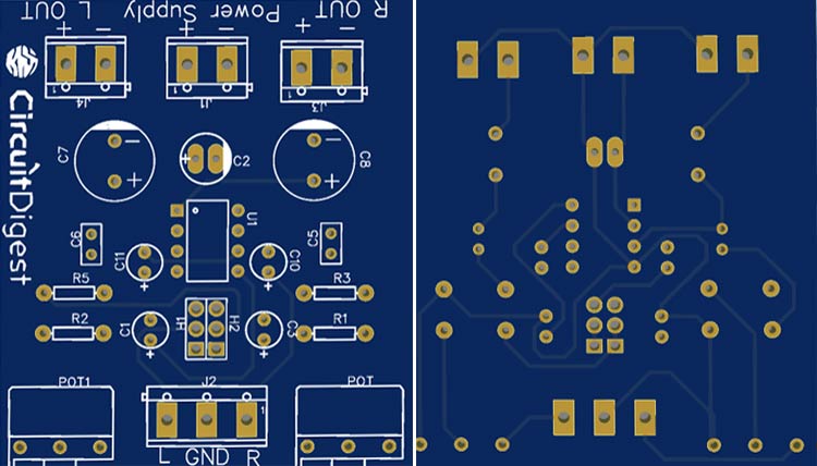
Once the schematic is done, we can proceed with laying out the PCB. You can design the PCB using any PCB software of your choice. We have used EasyEDA to fabricate PCB for this project. You can view any Layer (Top, Bottom, Topsilk, bottom silk, etc.) of the PCB by selecting the layer from the ‘Layers’ window. Apart from this, you can also see the 3D model view of the PCB on how it would appear after fabrication. Below are the 3D model views of the top layer and bottom layer of Pi Motor Driver HAT PCB.
The PCB layout for the above circuit is also available for download as Gerber from the link given below:
Now after finalizing the design, you can proceed with ordering the PCB:
Step 1: Go to https://www.pcbway.com/ and sign in. Sign up if this is your first time. Then, in the PCB Prototype tab, enter the dimensions of your PCB, the number of layers, and the number of PCBs you require.
Step 2: Proceed by clicking on the ‘Quote Now’ button. You will be taken to a page where you will have to set a few additional parameters like the Board type, Layers, Material for PCB, Thickness, and more; most of them are selected by default, if you are opting for any specific parameters, you can select accordingly.
Step 3: The final step is to upload the Gerber file and proceed with the payment. To make sure the process is smooth, PCBWAY verifies if your Gerber file is valid before proceeding with the payment. This way, you can be sure that your PCB is fabrication friendly and will reach you as committed.
After a few days of ordering, we received our TDA2822 PCB board in a neat package and the PCB quality was good as always. The top layer and the bottom layer of the board are shown below:

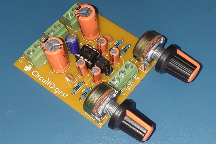
After making sure the tracks and footprints were correct, I proceeded with assembling the PCB. The completely soldered board looked as shown in the image below:
Once you finish assembling the PCB, connect speakers to the left and right channel output pins. The IC output power depends on the input supply voltage and output load. The power output from the in-built operational amplifiers of the IC has been summarized in the table given below.

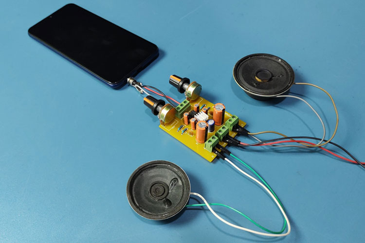
For testing purposes, I connected two 32 ohm speakers and powered the IC using a lithium polymer battery. The audio input is provided from a smartphone. For receiving audio from the smartphone, an audio jack of 3.5 mm is plugged into the phone and you are done.